
Finding a Hidden Solder Defect Without Opening the Assembly
- Industry
Richard J. Forbes
- 0
- 4 minutes read
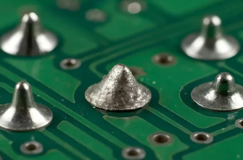
A board passes every functional test on the line. Then it fails intermittently in the field, weeks later, for no reason anyone can reproduce.
The assembly looks fine from outside. Nothing about it suggests a problem.
Somewhere inside a sealed connection, though, a solder joint never fully formed. That’s exactly the kind of defect x-ray inspection for electronic components exists to find.
The defect nobody can see from outside
Solder voids, misaligned components, and hidden internal damage all share one trait. None of them show up on a visual inspection.
A component can sit slightly off its pad and still solder down. It can look connected while carrying a weak or incomplete joint underneath.
Opening the assembly to check would usually destroy it, or at minimum invalidate the unit for actual use. That leaves imaging as the only realistic option.
How an x-ray image forms without film
An X-ray source passes beams through the assembly, and different materials absorb different amounts of radiation. Dense metal, like solder, blocks more of the beam than the surrounding plastic and silicon.
That difference in absorption creates a latent image on a digital detector. No film. No chemical development. The image appears directly on a screen, ready to be examined immediately.
The readout can be filtered and enlarged right there on screen, which makes small defects easier to catch than they’d be on a printed film image from older radiography methods.
What shows up: voids, misalignment, hidden damage
A handful of defects show up consistently once an assembly goes under the beam.
- Solder voids inside BGA connections, invisible from any external angle
- Components sitting slightly misaligned on their pads
- Internal cracks or damage inside a sealed or encapsulated part
- Incomplete solder joints that look connected but carry a weak bond
- Foreign material trapped inside an assembly during manufacturing
Each of these can cause a failure that never shows up during initial functional testing. The unit works, right up until it doesn’t.
Why speed beats depth for most assemblies
A full 3D scan would catch everything a flat 2D image catches, and more. Most production lines don’t have time for that level of detail on every unit, though.
2D imaging trades some depth information for real-time speed. A board can be screened in seconds rather than minutes, which matters enormously when a production run needs checking at volume rather than one unit at a time.
That tradeoff makes sense for most assemblies. A quick flat image is usually enough to catch a misaligned part or an obvious void without slowing the line down.
Knowing when a flat image isn’t enough
Sometimes a 2D image isn’t sufficient on its own. Densely packed boards can have features that overlap in a flat image, hiding a defect directly behind another component.
That’s the point where three-dimensional imaging becomes worth the extra time. A defect hiding behind a dense component in x-ray inspection for electronic components might never show up on a flat scan, but it would appear clearly once the data can be sliced apart in three dimensions.
For most production screening, though, a flat image catches the problem fast enough to matter. The extra depth only earns its cost once something specific demands it.

